Honda HR-V: Transfer Assembly Disassembly and Reassembly (CVT)
Special Tools Required
Oil Seal Driver Attachment, 58 mm 07JAD-PH80101
Holder, Companion 07PAB-0020000
Driver, 32.5 mm 070AD-SAA0100
Driver Handle, 15 x 135L 07749-0010000
Exploded View
1. Transfer Assembly - Exploded View
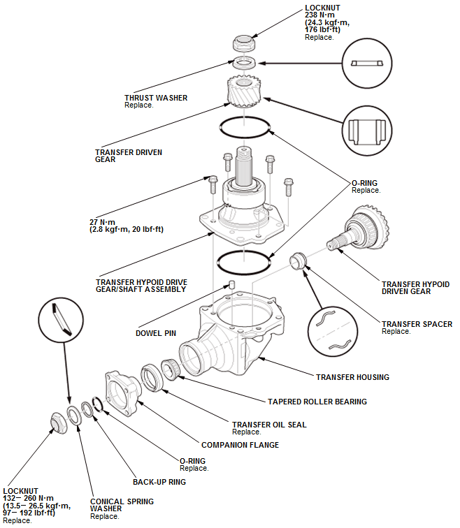
Fig. 56: Exploded View Of Transfer Assembly With Torque Specifications
Disassembly
1. Transfer Hypoid Drive Gear/Shaft Assembly - Remove
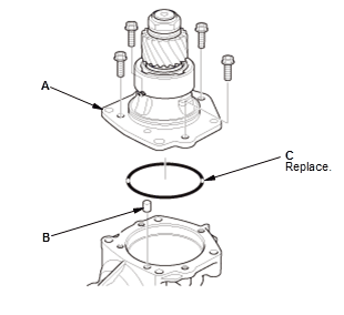
- Remove the transfer hypoid drive shaft assembly (A), dowel pin (B) and the O-ring (C).
2. Transfer Driven Gear - Remove
- Pry up the stake (A) on the locknut (B).
NOTE: Make sure the tab completely clears the groove to prevent damaging the shaft.
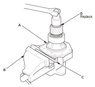
- Secure the transfer hypoid drive gear/shaft assembly (A) in a bench vise (B) with hex wrench (C)
- Remove the locknut (D).
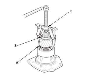
- Remove the transfer driven gear (A) and the thrust washer (B) using a puller (C).
3. Companion Flange - Remove

- Pry up the stake (A) on the locknut (B).
NOTE: Make sure the tab completely clears the groove to prevent damaging the shaft.
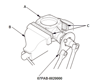
- Secure the transfer housing (A) in a bench vise (B).
NOTE: To prevent damaging the transfer housing, always use wood blocks or equivalent materials (C) between the transfer housing and the bench vise.
- Install the companion holder on the companion flange.
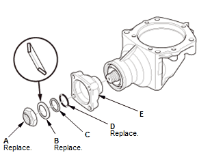
- Remove the locknut (A), the conical spring washer (B), the back-up ring (C), the O-ring (D), and the companion flange (E).
4. Transfer Hypoid Driven Gear - Remove

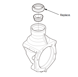
- Remove the transfer hypoid driven gear (A) with the transfer spacer (B).
5. Transfer Oil Seal - Remove
Reassembly
1. Transfer Oil Seal - Install
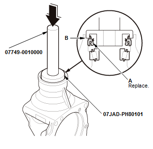
- Install the transfer oil seal flush with the transfer housing using the 15 x 135L driver handle and the 58 mm oil seal driver attachment using a press as shown.
2. Transfer Hypoid Driven Gear - Install
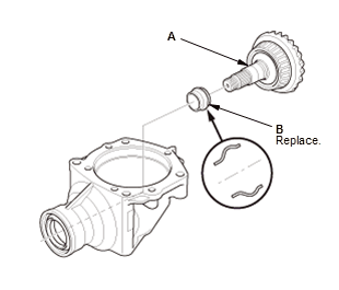
- Install the transfer hypoid driven gear (A) with the a new transfer spacer (B).
3. Companion Flange - Install
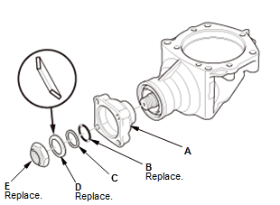
- Install the companion flange (A), a new O-ring (B), the back-up ring
(C), a new
conical spring washer (D), and a new locknut (E).
NOTE: Install the conical spring washer in the direction shown.

- Secure the transfer housing (A) in a bench vise (B).
NOTE: To prevent damaging the transfer housing, always use wood blocks or equivalent materials (C) between the transfer housing and the bench vise.
- Install the companion holder on the companion flange
- Tighten the locknut while measuring the starting torque of the transfer output shaft (hypoid gear) so the starting torque is within 0.98-1.39 N.m (10.0-14.2 kgf.cm, 8.7-12.3 lbf.in). Tighten the locknut to the lower torque specification, then check the starting torque. If the starting torque is low, increase the torque on the locknut until the starting torque is acceptable.
Tightening Torque: 132-260 N.m (13.5-26.5 kgf.m, 97-192 lbf.ft)
Starting Torque: 0.98-1.39 N.m (10.0-14.2 kgf.cm, 8.7-12.3 lbf.in)
NOTE:
- Rotate the companion flange several times to seat the tapered roller bearings, then measure the starting torque.
- If the starting torque exceeds 1.39 N.m (14.2 kgf.cm, 8.2 lbf.in), replace the transfer spacer and reassemble the parts. Do not adjust the torque with the locknut loose.
- If the tightening torque exceeds 260 N.m (26.5 kgf.m, 192 lbf.ft), replace the transfer spacer and reassemble the parts.
- Remove the companion holder.
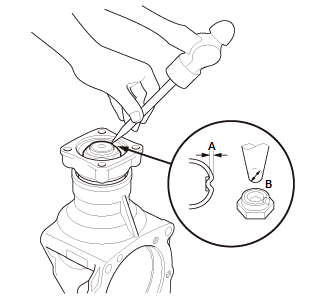
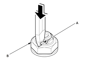
- Stake the locknut to a depth (A) of at least 0.7 mm (0.028 in) using a
3.0-3.5 mm
(0.118 in-0.138 in) punch (B).
NOTE: Be careful not to crack the locknut when staking.
4. Transfer Driven Gear - Install
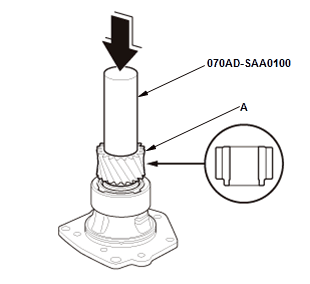
- Install the transfer driven gear (A) using the 32.5 mm driver
attachment.
NOTE: Install the transfer driven gear in the direction shown.
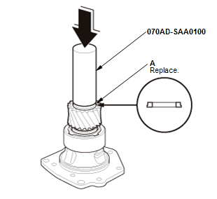
- Install a new thrust washer (A) using the 32.5 mm driver attachment.
NOTE: Install the thrust washer in the direction shown.
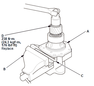
Fig. 57: Transfer Hypoid Drive Gear/Shaft Assembly Locknut With Torque
Specifications
- Secure the transfer hypoid drive gear/shaft assembly (A) in a bench vise (B) with hex wrench (C)
- Install a new locknut (D).
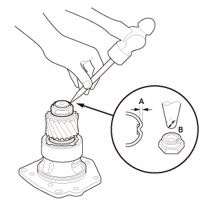
- Stake the locknut to a depth (A) of at least 0.7 mm (0.028 in) using a
3.0-3.5 mm
(0.118 in-0.138 in) punch (B).
NOTE: Be careful not to crack the locknut when staking.
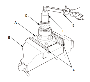
- Secure the transfer hypoid drive gear/shaft assembly (A) in a bench vise
(B).
NOTE: To prevent damaging the transfer housing, always use wood blocks or equivalent materials (C) between the transfer housing and the bench vise
- Rotate the transfer driven gear (D) in both directions to seat the bearings
- Measure the starting torque of the transfer hypoid drive gear/shaft assembly using the torque wrench (E), and a socket (F).
Starting Torque: 1.63-5.23 N.m (16.6-53.4 kgf.cm, 14.4-46.3 lbf.in)
- If the starting torque is out of the standard, replace the transfer assembly.
5. Transfer Hypoid Drive Gear - Tooth Contact Pattern Check
6. Transfer Hypoid Drive Gear/Shaft Assembly - Install
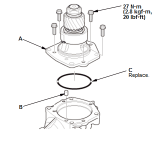
Fig. 58: Transfer Hypoid Drive Gear/Shaft Assembly With Torque Specifications
- Install the transfer hypoid drive shaft assembly (A), dowel pin (B) and a new O-ring (C).
7. Transfer Assembly - Total Starting Torque Check
8. Transfer Assembly - Transfer Gear Backlash Check
READ NEXT:
 Component Location Index
A/T GEAR POSITION INDICATOR COMPONENT LOCATION INDEX (CVT)
Without paddle shifter
With paddle shifter
A/T INTERLOCK SYSTEM COMPONENT LOCATION INDEX (CVT)
CVT DIFFERENTIAL COMPONENT LOCATION INDEX
How to Information
HOW TO TROUBLESHOOT THE CVT SYSTEM (CVT)
How to Check for DTCs with the Honda Diagnostic System (HDS)
When the powertrain control module (PCM) senses an abnormality in the input
or output systems, th
Manual Transaxle - Service Information
Back-Up Light Switch Removal and Installation (M/T)
Removal
1. Air Cleaner - Remove
2. Back-Up Light Switch - Removal
Disconnect the connector (A)
Remove the back-up light switch (B).
Installatio
SEE MORE:
Front Door Glass Removal and Installation
Removal & Installation
1. Front Door Panel - Remove
2. Front Door Plastic Cover - Remove
Remove the plug caps (A)
Disconnect the connector (B)
Remove the harness clips (C)
Remove the front door plastic cover (D) as needed.
NOTE : If the plastic
cover is damaged or torn, replace it with a
SRS System Description - Front Passenger's Weight Sensor
The front passenger's seat is equipped with front passenger's weight sensors
to detect the presence and weight of the occupant to tailor the front
passenger's airbag deployment and performance in the event of a
collision. The front passenger's weight sensors are part of the front
passenger's seat
