Honda HR-V: DTC Troubleshooting B2840-13, B2841-13: SRS Unit Connector Not Properly Installed
Honda HR-V (2015-2021) Service Manual / Restraints / Supplemental Restraint System - Diagnostics / DTC Troubleshooting / DTC Troubleshooting B2840-13, B2841-13: SRS Unit Connector Not
Properly Installed
NOTE:
- Before doing this troubleshooting procedure, find out if the vehicle was in a collision. If so, verify that all the required components were replaced with new components of the correct part number, and that they were properly installed.
- Before doing this troubleshooting procedure, review SRS Precautions and Procedures, General Troubleshooting Information, and 12 Volt Battery Terminal Disconnection and Reconnection.
1. Problem verification:
- Clear the DTCs with the HDS.
- Turn the vehicle to the ON mode, then wait for 10 seconds.
- Check for DTCs with the HDS.
1. Problem verification:
- Clear the DTCs with the HDS.
- Turn the vehicle to the ON mode, then wait for 10 seconds.
- Check for DTCs with the HDS.
2. Connector connection check:
- Turn the vehicle to the OFF (LOCK) mode.
- Check the following connector connections.
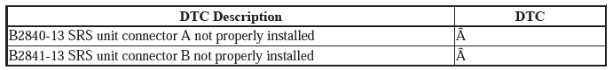
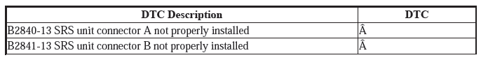
SRS unit connector A (39P)
SRS unit connector B (39P)
Are the connectors OK?
YES
Go to step 4.
NO
Go to step 3.
3. System check:
- Repair the poor connector connections whichever was the cause of the problem in step 2.
- Clear the DTCs with the HDS.
- Turn the vehicle to the ON mode, then wait for 10 seconds.
- Check for DTCs with the HDS.

Are DTC B2840-13 and B2841-13 indicated?
YES
Turn the vehicle to the OFF (LOCK) mode, then go to step 4.
NO
The system is OK at this time.
4. SRS unit check:
- Disconnect the negative cable from the 12 volt battery, then wait at least 3 minutes.
- Disconnect the following connectors.
SRS unit connector A (39P)
SRS unit connector B (39P)
- Check for bent or damaged terminals on the SRS unit.
Are any terminals bent or damaged?
YES
Replace the SRS unit.
NO
Replace the dashboard wire harness or the floor wire harness, then clear the DTC.
READ NEXT:
 DTC Troubleshooting U0101-00: Lost Communication with the PCM (SRS
Unit)
DTC Troubleshooting U0101-00: Lost Communication with the PCM (SRS
Unit)
NOTE:
Before doing this troubleshooting procedure, find out if the vehicle was
in a collision. If so, verify
that all the required components were replaced with new components of the
correct pa
DTC Troubleshooting U0155-00: Lost Communication with the Gauge
Control
MODULE (SRS Unit)
NOTE:
Before doing this troubleshooting procedure, find out if the vehicle was
in a collision. If so, verify
that all the required components were replaced with new components of the
correct pa
Advanced Diagnostics
DTC ADVANCED DIAGNOSTICS: SRS RELATED DTCS
NOTE
Always check "How to troubleshoot the SRS system" and proceed along each
"DTC Troubleshooting"
procedure.
Make sure the 12 volt battery is fully c
SEE MORE:
Front Seat-Back Cover Removal and Installation
Removal & Installation
NOTE : SRS components are located in this area. Review the SRS component
locations - Refer to: SRS
Component Location Index (KA/KC), or SRS Component Location Index (KA/KC) and
the precautions
and procedures before doing repairs or service.
1. Front Seat - Remove
2. Fron
Locking/Unlocking the Doors from the Inside
■Using the Lock Tab
■ Locking a door
Push the lock tab forward.
■ Unlocking a door
Pull the lock tab rearward.
When you lock the door using the lock tab on the
driver's door, all the other doors and the tailgate lock
at the same time.
When you unlock the door using the lock tab on the
driver
© 2019-2025 Copyright www.hohrv2.com
